Engineering
We are hiring a structural engineer, and this is the brief.
Most kit home companies publish a render and a waitlist. This is the specification instead: the geometry, the loads, the numbers we have, and every question still open with our engineer. The open questions are the part worth reading. Anyone can publish answers.
Nothing on this page is engineered, tested, stamped or approved. It is a specification and a set of intentions. No figure here may be relied on for permitting, for insurance, or for a decision to buy anything. When a Florida PE gives us a number we will publish it here with the report attached, and if it is worse than we hoped for we will publish that too.
What is being engineered
An eight sided single story dwelling of 1,600 square feet, about forty five feet across the flats, elevated on its own eight sided garage level. Structural concrete insulated panels, stood on site and sprayed with structural mortar on both faces, curing into a monolithic reinforced concrete shell with the insulation sealed inside. It is the largest geometry in the package and it is the one that governs the engineering, even though it is not currently for sale and 1200-3B is the one being built first.
We sell two kits. We want you to stamp four geometries. On sale today: the 400-1B, an accessory dwelling unit, slab only, 23 ft 4 in across the flats; and the 1200, 39 ft 4 in across, on a slab or raised on its own garage level, sold as a two bedroom or a three bedroom at one price because the walls that divide it are not the walls that carry it. Three stamped packages for sale, four interior layouts. No other options, no configurator.
The 1600-4B is in this package deliberately even though it is off the website. We narrowed the range to what a normal lot can take: an octagon needs its full width in both directions, so 45 ft 3 in across wants a 60 to 65 ft wide lot, and the median new American lot in 2025 was 8,543 sq ft. The 1200 fits that lot and the 1600 does not. But we do not want to pay to engineer this twice, so the 1600 stays in the package as the governing geometry and comes back to the price list on an acreage lot the day the market asks for it.
And they are small on purpose, which is a structural decision before it is a marketing one. The median new home completed in America last year was 2,142 square feet. Our three bedroom is 1,200. Panel is the dominant cost in this system and it scales with enclosed area, so every square foot we do not build is money the buyer can spend on a wall that survives the storm. Roof pitch, one centre wall instead of a cross, and seven foot walls are all the same decision applied three more times. If any of them is the wrong trade, this is the page where we want to hear it.
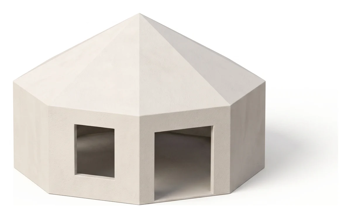 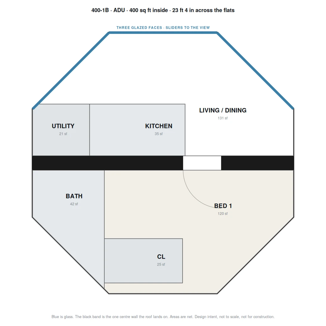 400-1B 400-1B | 400 sq ft to the inside face, 448 sq ft footprint, 23 ft 4 in across the flats, 2.45 panels a face, 1 bed 1 bath, positioned as an ADU, guest house or rental | $29,997 slab · not offered raised |
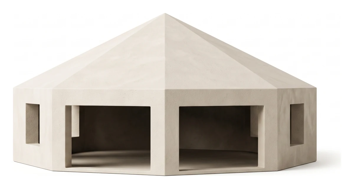 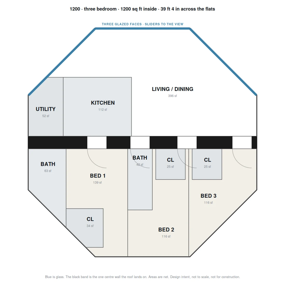 1200-3B 1200-3B | 1,200 sq ft to the inside face, 1,283 sq ft footprint, 39 ft 4 in across, 4.14 panels a face, 3 bed 2 bath | $59,997 slab · $99,997 raised |
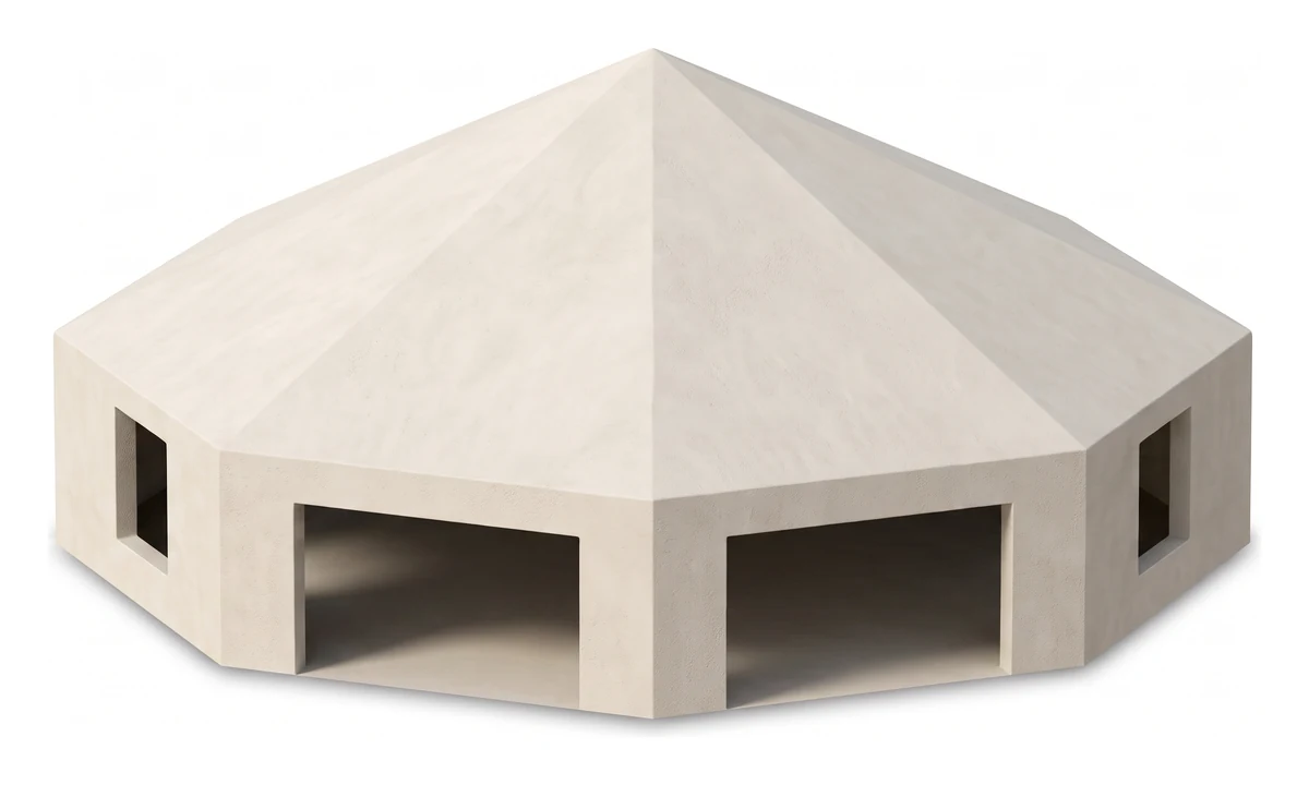 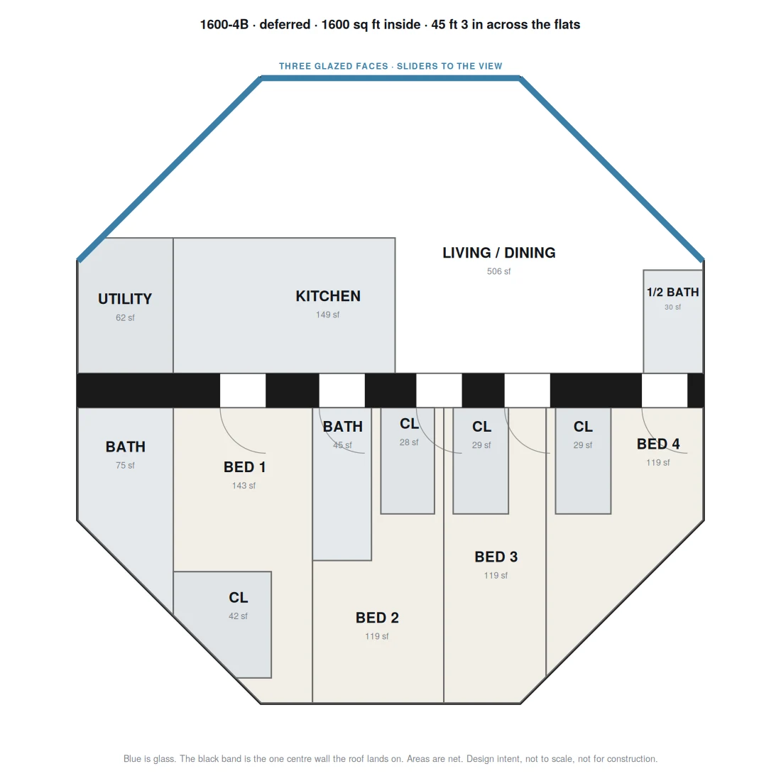 1600-4B 1600-4B | Not for sale, in the package as the governing geometry. 1,600 sq ft to the inside face, 1,695 sq ft footprint, 45 ft 3 in across, 4.76 panels a face, 4 bed 2.5 bath | deferred, not priced |
The floor area is the fixed input and the diameter is derived from it. That is the first principle of this design and it is backwards from how a kit is normally drawn. The model name is the square footage a person can stand on, measured to the finished inside face. If you change the wall thickness, move the diameter to hold the area. Do not hold the diameter and let the area drift, because the area is what we have sold.
Prices are estimates built from a modelled panel rate, not a supplier quote. A real quote is months away. They are published so a buyer can hold us to them, and they will move when it lands.
Panel takeoff, the whole product line
This is the quantity that has to be engineered and the quantity that gets quoted. Every panel is delivered hang ready: cut to final dimension for its position in the building, door and window openings formed at the plant with bucks, corner and edge mesh cut and folded with lap allowances, chases formed into the core, every panel marked and bundled by erection sequence.
| Package | Wall rate panel: shell, centre wall, all interior partitions, garage infill | Floor and roof panel | Total |
| 400-1B slab | 1,264 sq ft | 473 sq ft | 1,737 sq ft |
| 1200-3B slab | 2,316 sq ft | 1,352 sq ft | 3,668 sq ft |
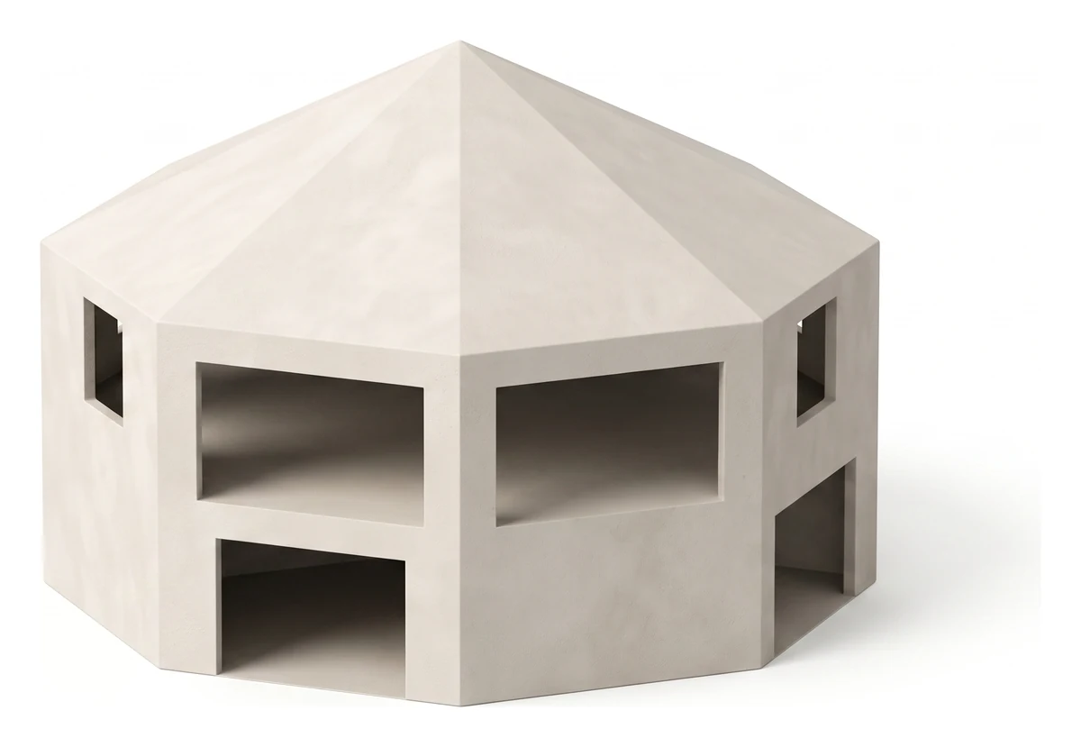 1200-3B raised 1200-3B raised | 3,670 sq ft | 2,635 sq ft | 6,305 sq ft |
| 1600-4B slab | 2,737 sq ft | 1,787 sq ft | 4,524 sq ft |
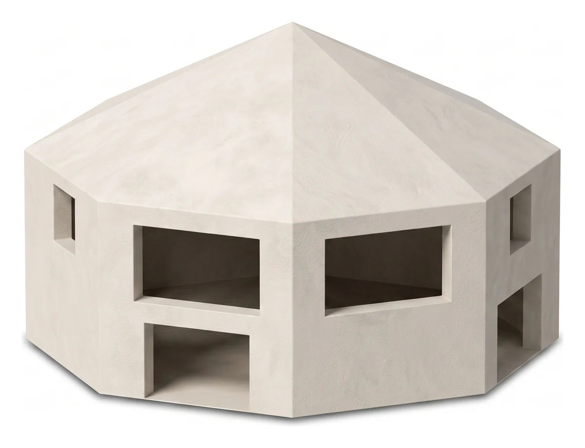 1600-4B raised 1600-4B raised | 4,293 sq ft | 3,483 sq ft | 7,776 sq ft |
Assumes a 9 ft wall panel, a 4.5:12 hip roof held across the whole line, garage infill at 55 percent of the perimeter with the balance open, vented or breakaway, and roughly 45 linear feet of partition beyond the centre wall on the largest package, scaled by floor area on the others. Every one of those is our assumption and not yet an engineered quantity.
One centre wall, not a cross, and whether that holds
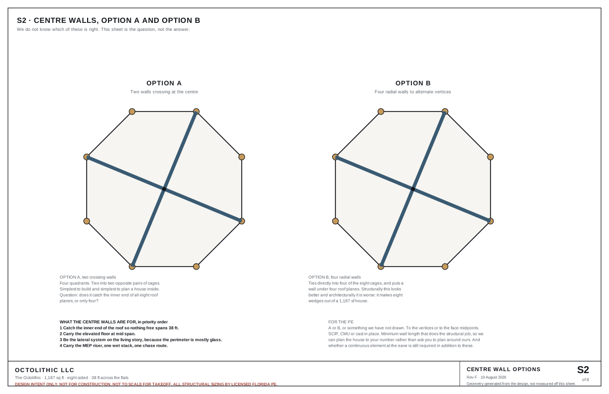
We want to replace the structural cross with a single wall on the diameter, and this is the question we most want answered. One wall running corner to corner through the centre. Its top follows the roof planes, tallest at the middle directly under the apex, dropping to eave height where it meets the perimeter. It props the apex where all eight hips converge and carries the two hips on its own axis. The other six still run eave to apex, but now against a supported point rather than a free one.
It is the primary interior support, the lap line for the floor and roof panels, and the wall between the sleeping side and the living side. One wall doing all three jobs. We supply every interior partition in the kit on every plan, so tell us which are structural and which are pure partition and we will mark and sequence them differently in the bundle.
The plan works at every size. Sleeping rooms and baths on one side, kitchen, living and dining open on the other:
| Package | Half the floor | Rooms, measured | Spare |
|---|---|---|---|
| 400-1B | 200 sq ft | 1 bed, 1 bath, 187 sq ft | 13 sq ft |
| 1200-3B | 600 sq ft | 3 bed, 2 bath, 560 sq ft | 40 sq ft |
| 1600-4B | 800 sq ft | 4 bed, 2.5 bath, 747 sq ft | 53 sq ft |
Those are not estimates. Every plan below is generated from the same octagon the shells are generated from, every room is clipped to it, and every area printed on the drawing is net, with anything sitting on top of a room subtracted from it. If a closet comes out too small to be a closet, the drawing does not build.
The four plans
One layout, four plans. Left to right on the sleeping side: master, bath, then the other bedrooms. The octagon is only full width for the middle band, so the corners get the rooms that can live in a wedge. The master ensuite and walk in take the canted outer end of the master's slice and the bed keeps the square part, with the centre wall as its headboard. Every bedroom door lands on the centre wall. There is no hallway anywhere in the range.
The three faces opposite the centre wall are glass, so nothing with cabinetry or a machine in it can go near them. The utility room, which holds the panel, the water heater and the laundry, and the kitchen beside it both back onto the centre wall. One wall, one stack, one electrical run, and the whole glazed perimeter left open.
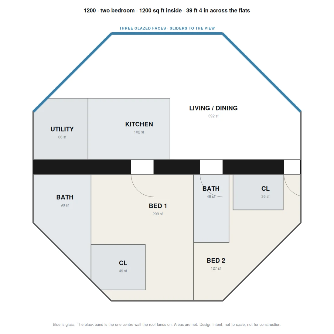
Two things on these we want you to push back on. The master ensuite sits on the outer wall rather than sharing the centre wall stack, which means a second plumbing run and, on the raised packages, a second penetration through the structural floor. And the utility room, the kitchen and the shared bath all load the same face of the centre wall. If either of those is a problem, we would rather move a room now than a stack later.
On the 1600-4B a single wall is about 637 sq ft of panel against roughly 1,200 for a full cross. That is the largest single material saving anywhere in this design, larger than roof pitch and larger than wall height put together.
Here is what worries us, and we would rather you told us we are wrong than agreed with us. A cross braces two axes. One wall braces one, and everything perpendicular to it relies on the closed octagonal hoop and the roof diaphragm. If that is not enough, say so and we will keep the cross. We also need to know whether a panel can span eave to apex once the apex is propped, or whether the six hips off the wall axis need something at mid span.
On the raised packages we have carried the interior support down through the garage level as well, assuming the elevated floor cannot span the full width between the eight corner cages unaided. A 45 ft clear span on 1600-4B almost certainly needs it. A 23 ft span on 400-1B may not. If the two smaller packages can carry the elevated floor on the eight cages alone, that is 419 and 583 square feet of panel out of the kit and it changes the price of both.
So the question is not how long the walls have to be. It is where they are allowed to go, what we can open through them for doors, and at what clear span the garage level version stops being required. A structural wall with a door in it is a wall with a header in it, and we want that detail once, parametrically, rather than improvised per plan.
This has to be stamped parametrically, and that is a requirement
We need the package to cover the family as one system with a size table and a span limit, not as three separately stamped buildings. It is the condition that makes the rest of this affordable, so please tell us up front whether you can do it, because if you cannot we need to know before we commission anything.
These are not three designs. They are one octagon at three diameters: the same eight panels, the same corner cages, the same single centre wall on the diameter, the same 4.5:12 roof, the same connector, the same base plate. Only the width across the flats changes, at 23 ft 4 in, 39 ft 4 in and 45 ft 3 in. The interior partitions vary by layout and none of them are structural, which is why one shell can be sold as a two bedroom or a three bedroom without touching the engineering.
What that has to buy us: adding a diameter inside the stamped span limit, or changing an interior partition schedule, must not require a new stamp. If a size or a layout outside the table needs re-engineering, say so and tell us where the boundaries are, because those boundaries become our product line.
Please quote it three ways, so we can see the shape of it: one model stamped on its own, the family stamped as a system, and each of the three priced separately. We would also like to know at what unit volume a Florida Product Approval starts paying for itself against site specific stamped plans per buyer, because until it does, per house is the only version we can afford.
One pitch, not one rise, and how shallow you will let us go
We had been specifying a roof rise per model, which was a mistake. Rise is an absolute height and the models are different widths, so it produced five different roofs: the shed came out at 9.1:12 while the 1600-4B was 6.4:12. They did not read as one building because they were not one building. We now hold the whole line to 4.5:12 and derive every rise from it.
| Package | Across flats | Rise, derived | Was | Peak ceiling |
|---|---|---|---|---|
| 400-1B | 23 ft 4 in | 4.37 ft | 7.0 ft, 7.2:12 | 13.4 ft |
| 1200-3B | 39 ft 4 in | 7.37 ft | 10.5 ft, 6.4:12 | 16.4 ft |
| 1600-4B | 45 ft 3 in | 8.48 ft | 12.0 ft, 6.4:12 | 17.5 ft |
That takes roughly $3,200 of panel out of the five models. Floor and roof panel is 53 percent of our panel cost on 40 percent of the area, so this is where material reduction lives, not in wall height.
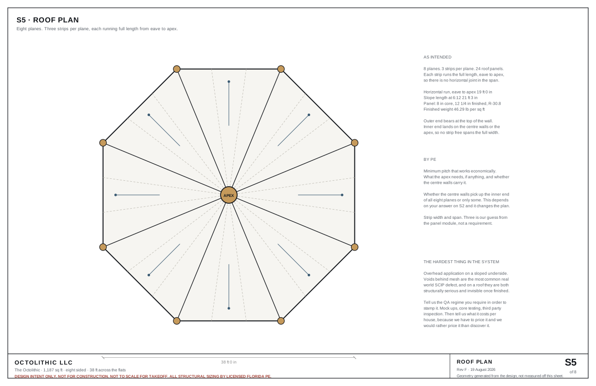
Why we stopped at 4.5:12 rather than going flatter. Not snow. We build in Florida, where the ground snow load is zero, and we are not designing a roof for a load that does not occur. Tell us if that is wrong. Two things stopped us instead. Our understanding is that below roughly 4:12 the windward slope suction gets worse rather than better, so tell us the shallowest pitch you will stamp. And a faceted pyramid carries part of its load in compression down the hips, which depends on the rise: flatten it and it behaves more like a plate in bending while outward thrust at the eave grows roughly as one over the rise. Halving the rise doubles the ring tension. At 4.5:12, tell us what the top ring has to be, and whether we are simply spending in the ring what we saved in panel.
The returns are shrinking anyway. On the 1600-4B the first two feet of rise removed saved about $668; each further foot saves under $200 while the thrust keeps climbing. If 4.5:12 is too shallow, say so and we will raise it. The number matters less to us than holding one number across the whole line.
Wall height, and why we are not cutting it
We looked at dropping the walls from 9 ft to 7 ft to save panel. We are not doing it, and the reason is the door head rather than the money. A standard exterior door head sits at 6 ft 8 in, which is 80 in. A 9 ft wall leaves 28 in above it. An 8 ft wall leaves 16. A 7 ft wall leaves 4 in, which is not a lintel, it is a gap. The strip of wall over every opening is what carries roof bearing across it and what the mesh laps into. A 7 ft slider head in a 7 ft wall leaves nothing at all.
The saving was never the argument: 7 ft walls take about 300 sq ft of panel off the 1600-4B, roughly $1,800, and would put a 7 ft ceiling against a 7 ft habitable minimum with no margin for a floor finish. 9 ft walls stay. Confirm the head band you want us to hold above every opening, because it drives every door and window on every plan.
Elevation is a variable, not a fixed story
Base flood elevation differs lot to lot across Florida, so the height of the garage level is an input rather than a constant. We do not want a design that only works at one height. Engineer the raised packages parametrically over a range of roughly 5 ft to 12 ft of elevation and tell us where the answer changes: where the cages need a different section, where the infill stops being able to be breakaway, and where the whole approach stops working.
The published prices assume 9 ft. A buyer whose lot needs 5 ft should pay for 5 ft, and we quote it down rather than keeping the difference.
Flood zone, and whether the eight cages qualify
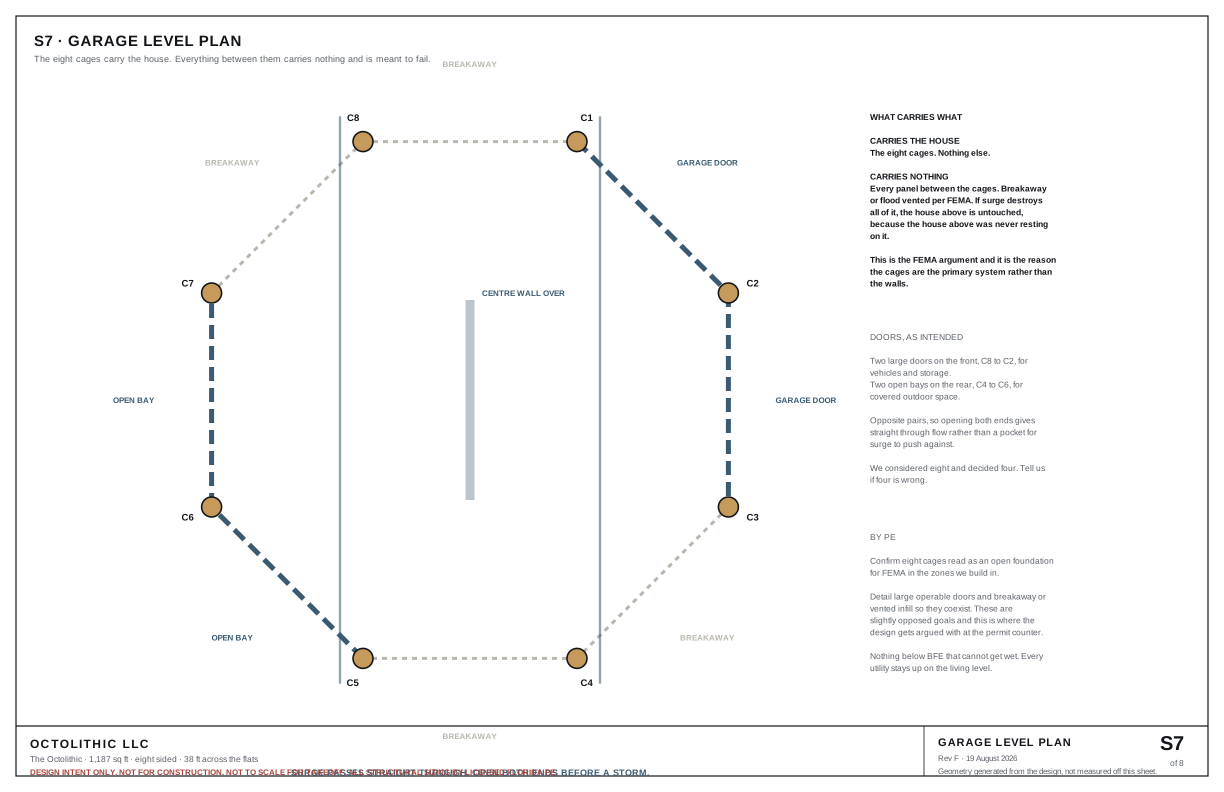
In a FEMA VE zone slab construction is not permitted and the foundation must be pile or pier, with the space below base flood elevation limited to breakaway walls. In an AE zone the lowest floor must sit at or above base flood elevation, with flood vents in any enclosure below.
We believe the eight reinforced concrete cages qualify as a pier foundation and that the infill between them can be breakaway or vented as the zone requires. We need that as your written conclusion, not our assumption, because it decides whether these can be sold into VE at all, and a coastal Florida lot is exactly where this product is supposed to make sense.
Each face is 2.45, 4.14 or 4.76 panels wide at the 1,200 mm machine width, so one panel on each of the eight faces is ripped narrower than the rest: a 537, 486 or 168 mm strip. We need you to confirm a ripped panel develops its strength once re-edged, and we need the panel maker to confirm they will rip width at all. If either answer is no, say so and we will move to the nearest half panel rather than compromise the structure, and we will publish the revised areas rather than hold the names. Material waste from the rips is about one panel a level, roughly $250. The waste is not the issue. The mesh is.
The panel specification, decided
| Exterior walls | 5 in core, 7 3/4 in finished, R-19.3 | 21.75 lb/sq ft |
| Centre walls | 4 in core, 6 3/4 in finished, interior structural | 21.50 lb/sq ft |
| Interior partitions | 2 in core, 4 3/4 in finished | 21.32 lb/sq ft |
| Floor and roof | 8 in core, 12 1/4 in finished, R-30.8 | 46.29 lb/sq ft |
R values are for the complete assembly at 70 degrees including the concrete on both faces, not for the insulation alone. Core to ASTM C578, mesh 11 gauge galvanized to ASTM A1064 at 115 ksi, applied mortar over 2,500 psi. Final thicknesses are subject to the engineer. We picked the second thickest of five floor panels rather than the thickest, because the top of the range adds nearly ten tons of dead load on the roof and every pound of it lands on the corner cages and the foundation.
The structure
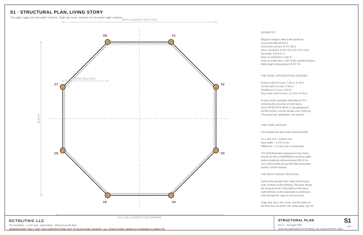
Eight reinforced concrete cages, one at each corner, eight per level. They stack on the same eight vertices and they carry the house. The walls of the garage level carry nothing: between the cages the infill is breakaway or vented, so surge passes through without loading the structure, and if it is destroyed the house above is untouched, because the house above was never resting on it.
Two structural walls cross at the centre of the plan, and they are also the interior walls. They divide the bedrooms, the baths, the kitchen and the laundry, they catch the inner end of the floor and the roof so that nothing spans thirty eight feet, and they are the lateral system on a level where most of the perimeter is glass.
What we are aiming at
These are targets, not ratings. They are what we have told an engineer to aim for. None of them has been achieved, tested or stamped.
Design pressure of plus and minus 124 psf or better, and qualified for use inside the High Velocity Hurricane Zone.
That number is not ours. It is the registered design pressure on Florida Product Approval FL30050-R4, held by a competitor, HVHZ approved and impact resistant. We chose a benchmark somebody else already holds so that we cannot quietly move it.
Two numbers circulating in this industry that we refuse to use. One converts a 124 psf design pressure into 283 mph by division, applying no pressure coefficient. The other converts a 90 mph missile impact test into "approximately 225 mph hurricane conditions". A missile impact velocity is a real test result. The conversion to a wind speed is arithmetic wearing weather. We hold every other kit maker to that distinction, which is why our own listing publishes no design wind speed at all.
The questions nobody has answered
This is the honest part, and it is the reason this page exists.
| Is HVHZ reachable? | No SCIP evaluation report we have read covers the High Velocity Hurricane Zone and one puts it explicitly out of scope. If the answer is no, the Keys and Miami-Dade are not our market, and we will say so here. |
| Does it stand unbraced? | Every panel maker's published erection sequence ends with temporary bracing. Ours does not, on purpose, and we have asked the engineer to break that argument if it deserves breaking. |
| Closed construction? | If these panels are closed construction under Florida Statute 553.36, they cannot be installed in Florida without a state approval and an insignia affixed at the plant. We are asking the department directly. |
| What roof pitch? | Pitch drives the thrust at the eave and we have not fixed it. We will move the house to the engineer's answer rather than the other way round. |
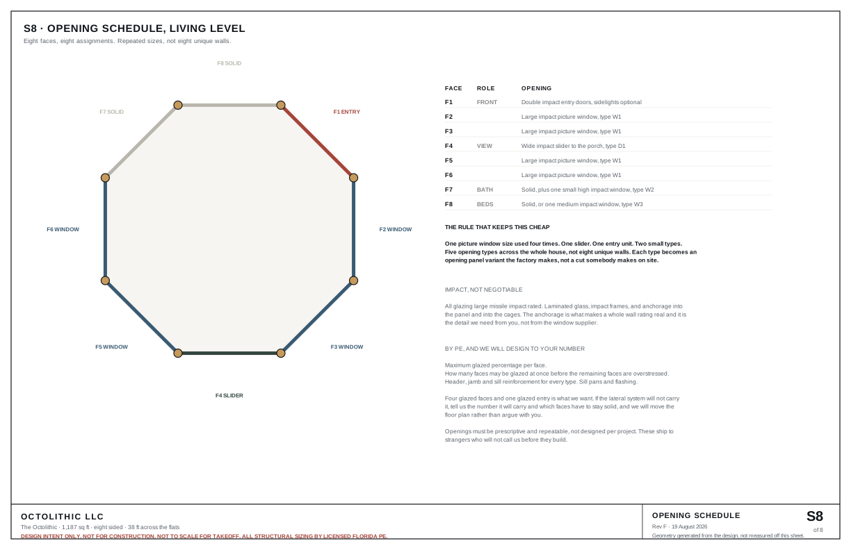
| How much glass? | How much of the perimeter can be glazed before the remaining faces are overstressed. |
| Piles or not? | Whether the corner cages need deep foundations, and at what soil condition. We are braced for the answer being piles. |
The drawings
Five of the eight design intent sheets. Three are held back, because the base plate geometry, the corner cage splice and the erection sequence are subject to a pending provisional application. Those go out under an NDA and not before.
Every dimension on these is generated from the geometry rather than drawn by hand, so a figure on one sheet cannot disagree with the same figure on another. Anything the engineer is being asked to determine is marked BY PE rather than given a number, because a plausible invented number is worse than a blank on a drawing somebody is going to design from. Design intent only. Not for construction.
If you are a Florida PE
We want stamped, permittable drawings, and we want to start now. Not a feasibility study. The full brief runs about twenty pages with an eight sheet drawing set, and we will send it the day you ask.
Four things worth knowing before you call. The drawings go to owner builders, so every detail has to be prescriptive and survivable by somebody reading it for the first time. We sell goods only and never touch the site, so no detail can assume our supervision. All work is work for hire, owned outright, unlimited reuse, no royalty. And we will publish your work, including the parts where you tell us we were wrong.